
|
Product Details:
Payment & Shipping Terms:
|
| Accuracy Class: | 0.05 | Test Object: | Digital (electronic) CT VT |
|---|---|---|---|
| Test Function: | Ratio Error, Phase Angle Error, Polarity Test...etc | Analog Input Signal: | 0-10V (peak) |
| Application: | Smart Substation, CT PT Producer | Compatible: | With IEC61850 Protocol |
| Highlight: | 0.05 Substation Test Equipment,10V Substation Test Equipment,Electronic CT PT Test Equipment |
||
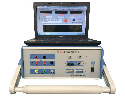
Electronic (Digital) CT &PT Calibrator HEWD-2A
Technical Parameters
| Primary rated voltage measure | up to 500KV |
| Primary rated current measure | 5-5000A, customization available |
| Standard signal input | |
| Voltage input | 0-120%Un, Un=100V,100/√3V. Customization available |
| Current input | 0-120%In, In=1A or 5A. Customization available |
| Analog input signal | 0-10V (peak value) |
| Small signal (sine wave) output | 0-4V (RMS value) |
| Accuracy class | |
| Ratio error | <0.05% (1-120% rated value) |
| Phase error | <2´(1-120% rated value) |
| Absolute delay | <1µS (waveform distortion less than 1%) |
| Delay jitter | <0.5µS |
| ST optical fiber interface (one group) | |
| Optical fiber Transmitting Power | >-6dBm |
| Optical Receiving sensitivity | -38dBm |
| Sync signal | |
| Optical PPS sync input & output | 4Nos |
| Optical IRIG-B(DC) sync input & output | 4Nos |
| Sync output time accuracy | better than 100ns |
| Input supply | AC220V±10%, 50/60HZ, power consumption less than 20W |
| Working condition | temperature 0℃~+55℃/Humidity ≤90% |
| Size & Weight | 360*400*160mm/7.5kgs |
Main Features
1. Digital output error test of electronic (digital) CT/PT
1) Ratio and phase error test
2) Compatible with the protocol IEC61850-9-1,IEC61850-9-2,IEC61850-9-2LE and IEC60044-FT3
3) Compatible with various optical fiber interfaces
4) Holography analysis of message of IEC61850-9-1/IEC61850-9-2
5) Recording error data of test point and data inquiry/store/print by software
2. Analog output error test of electronic (digital) CT/PT and conventional CT/PT
1) Ratio and phase error test of digital CT/PT
2) Ratio and phase error test of conventional CT/PT by converting into voltage signal through
standard converter
3. Up to test 0.2S class digital CT/PT
4. Analog of small signal output
5. Harmonic wave analysis of input signal of digital CT/PT under test, generation of spectrum curve,
record of content of each time harmonic (up to 50times harmonic), and calculation of harmonic distortion.
6. RMS value parameters analysis (amplitude, phase, frequency and etc) of input standard signal
7. Real-time displaying output waveform, standard signal waveform, polarity, sync status and percentage
value under test point of CT/PT under test
8. Polarity and time-delay test of digital CT/PT by using inbuilt PPS (pulse per second) and B code
to output sync signal
9. Operation by tablet through APP software (optional)
10. EMC compliance with standard IEC60044-8
11. PC software
1) Friendly HMI and clear interfaces
2) Automatically save test data and generate test report
Contact Person: Mr. Tony Han
Tel: 86-15237157117
Fax: 86-371-55692730